Overview
Purpose
The MIL-STD-461 RE102 test method defines how to measure radiated emission noise from electric units AND their electrical cables. Most people believe that EMI come from the unit itself, but most radiated emissions failures are due to currents on the cables which are excellent radiators. It is extreamly important to document the shielding requirements of your unit cables and to test how you fly.
The RE102 test has similarities to the automotive test method CISPR 25 but is significantly different from the general commercial testing standards including ANSI C63.4 and CISPR 32.
RE102 Limit Line
The standard RE102 limit line for aircraft and spacecraft applications from 10 kHz to 18 GHz is shown below when tested at 1 meter from the setup. For comparison, FCC testing requires conducted emissions testing from 30 MHz to a maximum of 40 GHz with distances of 3 meters and 10 meters. The limit is given as dBμV/m which is calculated from the linear electric field as 20*log10(E[μV/m]/1[μV/m]).
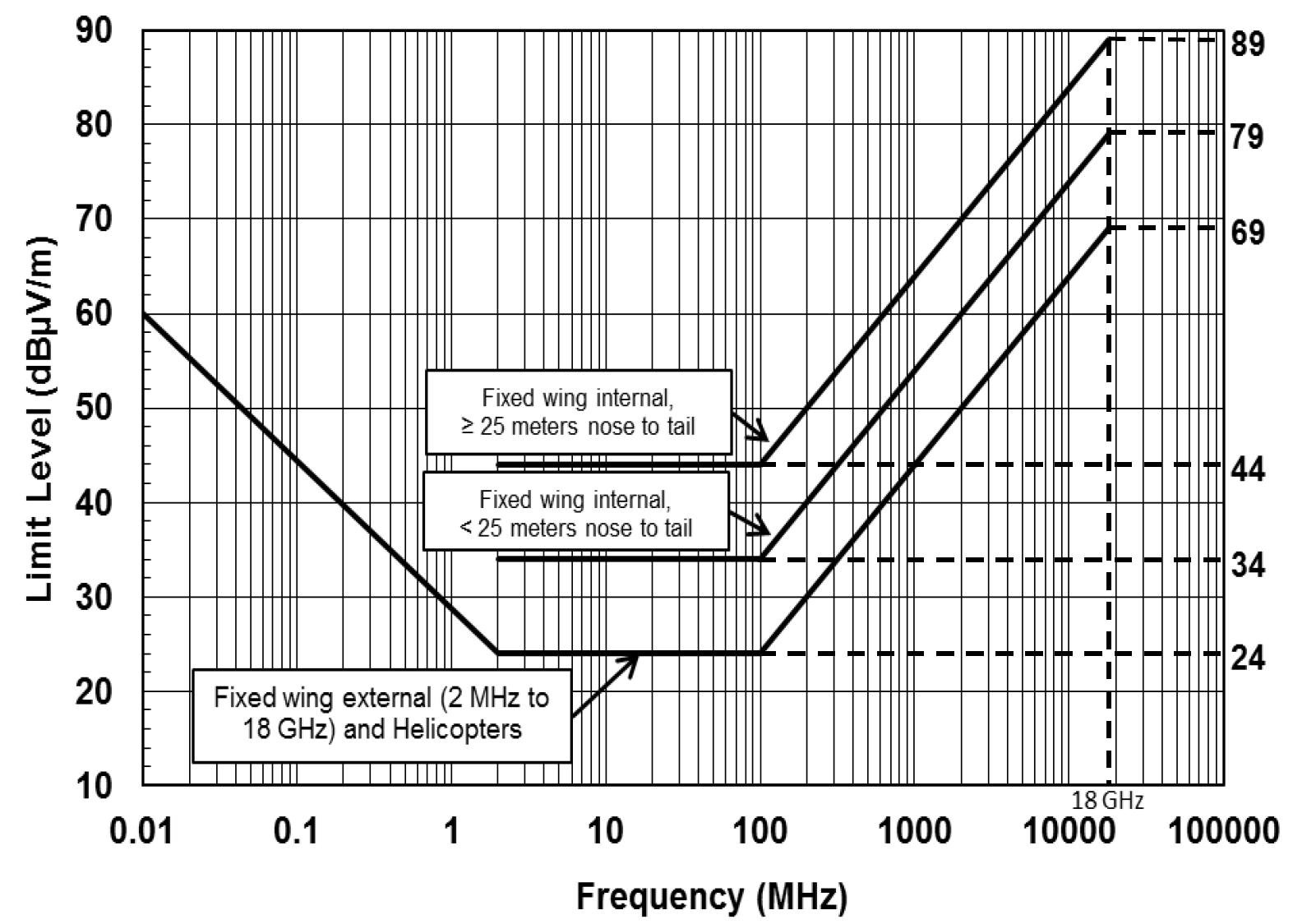
Keep in mind, the standard limits given in MIL-STD-461G are just a starting point and most programs require tailoring of the RE102 limits following MIL-STD-464 and it is very common to include receive band notches. Receive band notches for the lower GNSS band (1164 MHz to 1300 MHz), upper GNSS band (1559 to 1610 MHz), and S-band communications at 2200 to 2400 MHz are common. Whether the unit is placed inside the satellite faraday cage will affect the required RE102 limit for these receive band notches, but the notches generally range from 30 to 50 dBμV/m. A common practice for spacecraft EMC designers is to set a flat limit of 70 or 80 dBμV/m across the 10 kHz to 18 GHz range and add the receive band notches.
RE102 Test Setup
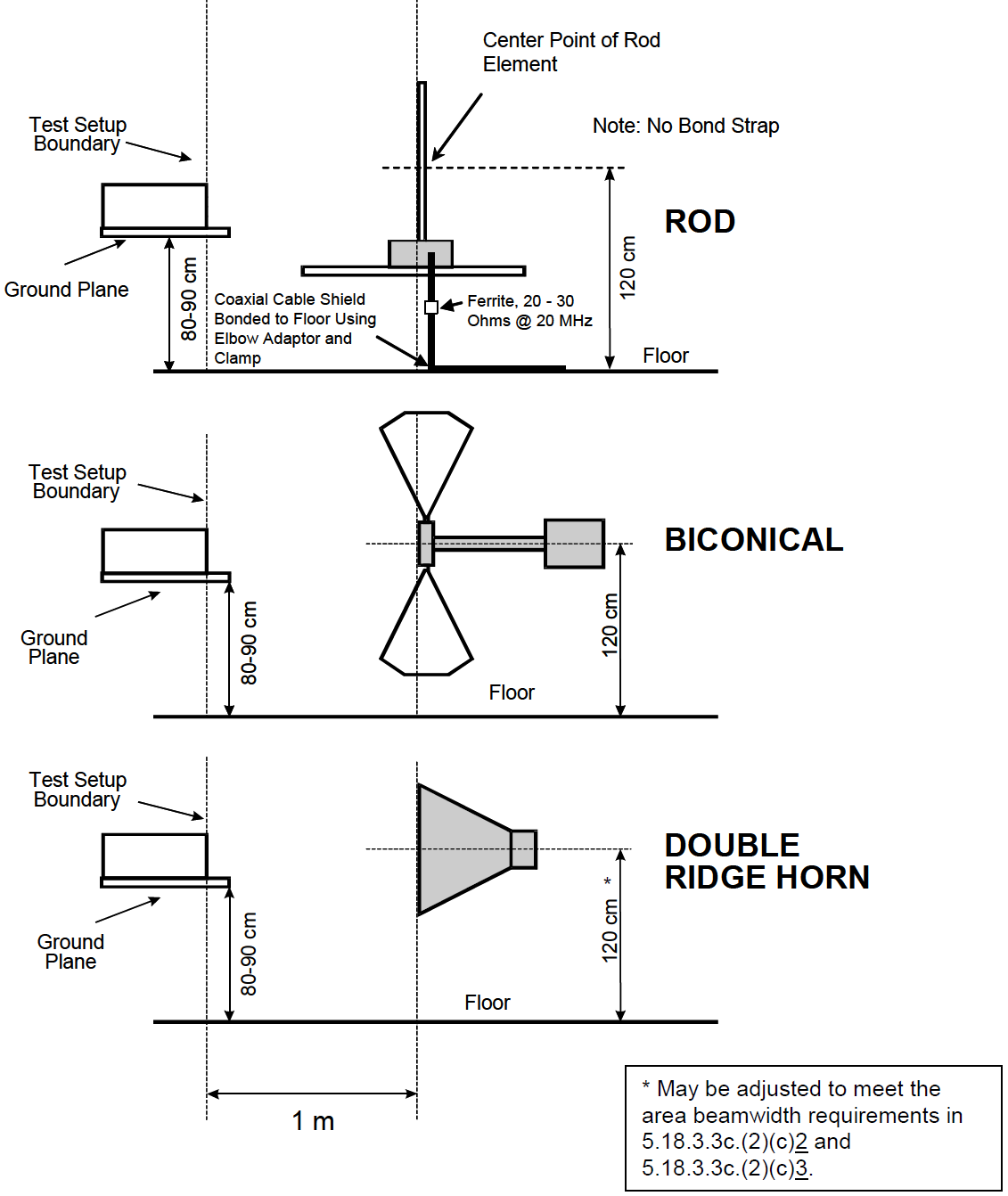
The diagrams of the general test setup and the RE102 antenna positioning is shown below. This is similar to the CE102 setup except that the LISN measurements ports are terminated.
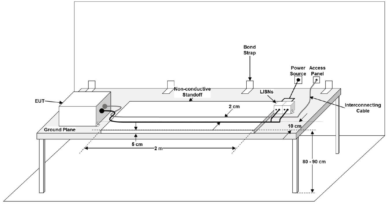
The standard RE102 setup shown above assumes that power will be unshielded and that the power and communication signals will be routed seperately but this is often not the case for 28 VDC applications where the power and communications are often routed together inside an overbraid shield. If your have a shielded harness and break out the power to the LISN, then the shield will be broken and RF currents allowed to penetrate the shield barrier. In this case, it is best to route the harnesses through the chamber bulkhead connector and terminate the power leads to a LISN outside the test chamber. This will maintian the overbraid shield and prevent RF currents to penetrate the shield barrier.
Design and Analysis
General Approach
Compliance to RE102 can be achieved using a combination of simulation and pre-compliance bench testing of a prototype. This section will cover some considerations in the steps involved.
RE102 Simulations
For simulations I perform radiated emission estimations in several steps. Each subsequent step will increase the accuracy of the emissions model. When simulations are required, I prefer to use circuit simulations with PSpice because they give deep understanding of the emissions and can be performed much faster than a full 3D electromagnetic solver.
- 1. Survey the unit for clocks and switching frequencies.
Every PCB and unit should be reviewed and the frequency, rise/fall times and modulation of the clocks and data communication lines recorded. The focus should be on high-speed interfaces or clocks including internally generated PLL clocks. The rise/fall times are important to calculate the largest frequency harmonic and can be estimated from the device datasheet or IBIS models of the drivers. Once this information is gathered, an assessment can be made if there are any especially high risks of RE102 exceedances due to clock harmonics in the receive band notches. In this step we are not estimating emissions levels, just performing an initial survey to determine what the generators are and what frequencies we could see them at. The Goal: Identify likely emission sources and their frequencies.
- 2. Create an EMC grounding diagram of your PCB.
Understanding how return current flows is central to controlling radiated emissions. The focus on the EMC grounding diagram is to identify 1) potential current return paths of external cabling and 2) potential internal return paths between PCB reference planes. This grounding diagram should be made on one large page and should include any filtering or shielding applied at the input and output interfaces. Both intentional and parasitic capacitance should be identified since these can dominate the high frequency responses. The Goal: Identify where the currents can flow from a big picture view. This can help us spot obvious problems early on.
3. Perform harness emissions simulations.
Most radiated emissions problems come from common mode currents on cables. The goal of this step is to 1) quantify the current on the cables and 2) estimate the radiated emissions from the currents. Calculating the cable currents is not easy but reasonable estimates can be made by constructing a coupling model from the EMI grounding diagram in step 2. Effects such as ground plane partial inductance, parasitic capacitance from PCB ground to chassis, and cable shielding must be included. Once the cable currents are modeled correctly then the emissions can be estimated using the EMI Sleuth RE102 cable emission in PSpice. The Goal:Quantifying the radiated emissions from the cables. This will help identify if additional filtering or shielding is required.
- 4. Perform direct PCB emissions simulations.
Simulations of emissions from PCBs should focus on exposed traces and possibly IC package leads of the high-risk sources found in Step 1. I usually start by estimating the longest exposed trace length. Sections of traces that are buried between ground planes with plenty of via stitching will be poor radiators and can be ignored. The emissions can be estimated with an IBIS driver model plus the EMI Sleuth RE102 emission estimator tool. If the emissions are over the limit, consider using a metal chassis and estimate the shielding effectiveness with the EMI Sleuth enclosure shielding effectiveness tool. The Goal: Quantify the emissions to determine what enclosure shielding is needed and how much.
- Caution:
The radiation emissions simulation method described above assumes you are following good practices for PCB design. Specifically, the loop area formed by the return current path must be minimized. Be generous with adding stitching vias, especially when signal traces change layers.
Avoid split ground planes because they will usually form unintentionally large radiation loop areas with the current return paths. Split ground planes can also make great patch antennas so the risk of unintentionally radiating high frequency harmonics of the clocking signals is significant. The technique of using split ground planes was more common when electronics were slower, but they are a band-aid solution that does more harm than good with modern high-speed electronics. Some older op amp datasheets recommend a split ground plane but most modern, and especially high speed, op amps recommend a solid ground plane.
Partitioning circuits by type (power, digital, analog) is always more effective at reducing noise coupling than attempting split ground planes. Applications that cannot tolerate a solid shared ground plane should already be using isolation circuits (i.e. digital isolators or optocouplers) to reduce coupling.
RE102 Pre-Compliance Testing
Testing your product before taking it to the lab for official EMC testing is the key to passing the first time. The EMC simulation discussed earlier can be useful in identifying risks early on, but these models are simplified and need to be validated with bench testing.
The hardest part of pre-compliance testing is controlling noise pickup from the environment. Ideally you will have a shielded room to test in, but that is not feasible for a lot of companies. Portable fabric EMI test chambers are a good option and can typically give 40 to 80 dB of shielding but can be expensive. Here are my recommendations for pre-compliance testing for RE102 outside of a shielded enclosure with a focus on emissions from 30 MHz to 3 GHz.
- 1. Get test equipment.
You will need a spectrum analyzer (or EMI receiver if you have one), a biconical antenna (30 MHz to 1 GHz), a horn antenna (1 GHz to 3 GHz min), and a RF current probe (ideally rated to 500 MHz or more). You will need test cables for connecting the DUT to the chamber feedthrough and the chamber feedthrough to your support equipment. Use the LISN from CE102 testing if it makes sense. Remember, RE102 is a test of the electronics AND the test cables so use realistic cables and if possible, use the same cables you plan to use in official EMC testing. The Goal: Buy, rent or make the right tools for pre-compliance testing.
- 2. Get a ground plane.
You will also need a conductive table to place the device and test cables on (see the general MIL-STD-461 setup above). This can be made by placing some aluminum sheet metal on a wooden table. For safety reasons this ground plane should be bonded to the power system equipment grounding conductor. Make a bulkhead connector at the edge of the table like where the shielded chamber feedthrough would go, this is critical if your cable is shielded. The Goal: Make your pre-compliance test setup as close to the MIL-STD-461 setup as possible.
- 3. Test with a current probe.
RF current probes are the best tool for measuring emissions coming from your cables. RF current probes are usually 20 dB more sensitive than a biconical antenna in open air, and this advantage becomes more pronounced when the cables are routed on a ground plane. They can also measure the common mode currents on individual lines and tell you exactly where the noise is leaking from. When taking measurements is best to set the spectrum analyzer to peak detect with maximum hold and then sweep the current probe along the cable slowly to detect the peak current along the cable. The current can be converted to an electric field using the EMI Sleuth RE102 cable emissions radiator. Caution: RF current probes have some limitations that should be considered when using them. The main disadvantage of RF current probes is that they have a relatively low maximum frequency, though some affordable current probes can operate at 750 MHz or higher. Another disadvantage is that they are sensitive to the position on the harness, since the currents will form standing waves with valleys and peaks. A third disadvantage is that they measure the current, and this needs to be converted to an electric field with an estimation.
The Goal: Measure the radiated emissions coming from common mode currents on the cables and see if more filtering or shielding is required.
- 4. Test with antennas.
The antennas can be used outside of a chamber but may pick up too much noise to be helpful. I recommend focusing on the frequencies above those taken with the RF current probe. To distinguish background noise from your EUT emissions I recommend taking three measurement cases:
- The noise measurement floor with the EUT powered off and the antenna located 1.0 m away. This will identify nearby transmitters.
- The emissions at 1.0 m with the EUT powered on and active.
- The emissions at 0.33 m with the EUT powered on and active. Emissions from the EUT should be 10 to 20 dB higher than emissions at 1 m away. No change may indicate that the emissions are coming from the support and control equipment which would normally not be picked up when using a shielded EMI chamber.
The Goal: Measure the radiated emissions coming from the electronics and the cables and identify required fixes before moving forward with testing.
Need Help?
If the steps above seem daunting or you run into problems along the way, then please reach out to EMI Sleuth for help in closing the analysis and getting the unit passing.