Description
Use the calculator above to estimate the shielding effectiveness of a rectangular metal enclosure with an aperture. The terms are defined as:
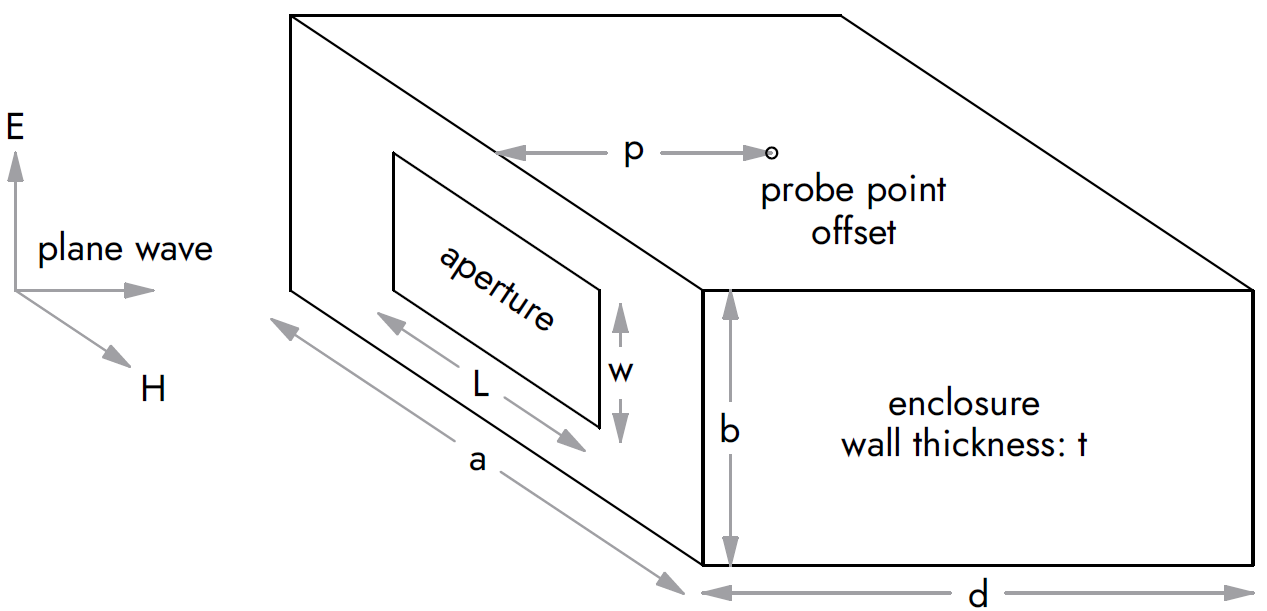
- a: Enclosure width
- b: Enclosure height
- d: Enclosure depth
- t: Enclosure wall thickness
- L: Aperture length (longest dimension)
- w: Aperture width
- p: Offset to probe point
- N: Number of identical apertures
- ζ: Cavity Damping/Loss Factor
- SE: Electric field shielding effectiveness of enclosure
- SM: Magnetic field shielding effectiveness of enclosure
The widely quoted shielding effectiveness equation by Henry Ott is used as a reference with SE = 20⋅log10(λ/2L) in dB. This is a simple and useful equation but neglects the internal resonances seen inside the cavity. It is also limited only to electric field shielding.
A more accurate model was given by Robinson [1] using the parameters listed above. This model includes the effects of cavity resonances, damping from losses inside the cavity, and multiple apertures. The paper should be read for a full understanding of the model limitations, but here are a few specific limitations of this calculator tool:
- The aperture dimensions are restricted to: L > w, L < a/√2, w < b/√2 .
- The probe point must stay inside the enclosure: d⋅0.01 ≤ p ≤ d⋅0.99 .
- The total area from all apertures must be less than 25% of the area of the enclosure face.
- The maximum frequency is limited to the lesser of: TE02 cutoff frequency, TE11 cutoff frequency, or 18 GHz.
- Light damping (ζ=0.5) is representative of an enclosure with a PCB installed inside the cavity.
- Heavy damping (ζ≥1.0) is representative of an enclosure with RF absorbing material installed inside the cavity.
References
- [1] M. P. Robinson et al., "Analytical formulation for the shielding effectiveness of enclosures with apertures," in IEEE Transactions on Electromagnetic Compatibility, vol. 40, no. 3, pp. 240-248, Aug. 1998. (IEEE Xplore Link)